Setting up Cisco SG300
Constructing a Virtual Local Area Network (VLAN)
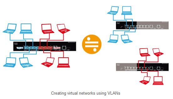
In a system that includes other types of networked devices than Dante, or a large-scale system that comprises of many Dante devices, you can avoid unnecessary packet transfers between the different types of device and make the network more stable by segmenting it. Ideally, a separate number of switches should be prepared for each network segment, but you can reduce the required number of switches and cables by using VLANs to create network segments. This method can reduce maintenance costs as well.
Network segmentation refers to the creation of virtual local area networks (VLANs) that are distinct from physical connections. When there are different types of networked devices within a system, you can create VLANs so that while the networks may share the same physical switches, they function as separate virtual networks.
You can provide connections between switches for each VLAN, but you can also use VLAN tagging so that data for various VLANs can be transferred over a single trunk (cable). This enables you to create virtual networks that are separate from the physical wiring.
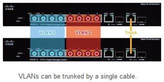
Here, we will present an example in which two VLANs are created and the switches are connected by a trunk. For example, in a live system using a CL/QL Series console, VLAN 1 (ports 1 and 2) could be used as the control network and VLAN 2 (ports 3 to 8) could be used as the Dante network.
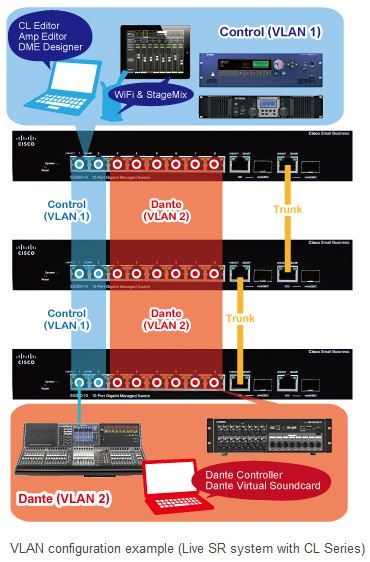
In the above example, it could also be said that VLAN 1 is the 100 Mbps control network while VLAN 2 is the broadband 1 Gbps network for audio transmission. By segmenting these networks, you can prevent the 1 Gbps network from overburdening the 100 Mbps network (although both networks coexist in the trunk). In the rest of this section, we will configure VLAN settings according to the example network configuration described above.
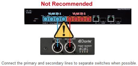
You can use network segmentation to connect the primary and secondary Dante lines to the same switch, but we recommend that you avoid doing this, because while connecting the lines to the same switch may provide the redundancy necessary for handling cable problems and other issues, if the switch malfunctions, both lines will be cut off.
Before you perform the following settings, make sure that the PC is connected to VLAN 1, which is the VLAN that you will be configuring first (in this example, the PC should be connected to port 1 or 2). VLAN 1 is a special default VLAN, so you should always connect the PC to a VLAN 1 port when you configure switch settings.
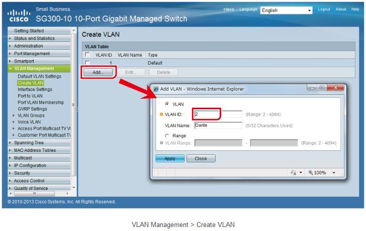
First, create the necessary VLAN. In the default settings, only VLAN 1 exists, so add VLAN 2. In the following page, click “Add”. In the VLAN ID box in the dialog box that appears, type “2”, and click “Apply”. When you are creating multiple VLANs, entering a VLAN name can help you identify each individual VLAN (but you do not have to enter a name).
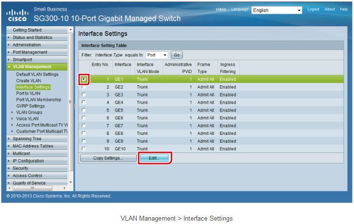
Next, you will need to set the VLAN mode for each switch port. By default, each port is a trunk port, so you will have to change ports 1 to 8 to access ports. In the following page, select port 1, and then click “Edit”.
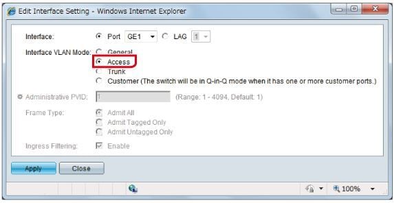
In the dialog box that appears, select “Access”.
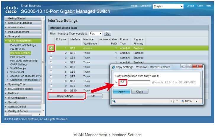
Change ports 2 to 8 to access ports in the same way. To set the ports more quickly, click “Copy Settings” while port 1 is selected, and copy the settings to ports 2 to 8.
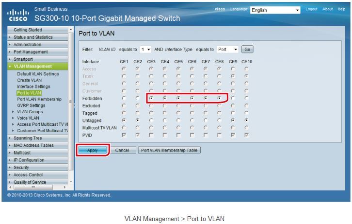
Next, assign each port to one of the VLANs. In the following page, you can specify which ports are allowed to access each VLAN. First, make sure that VLAN ID is set to “1” and Interface Type is set to “Port”. Ports 3 to 8 will not be included in VLAN 1, so set them to “Forbidden”. Ports 9 and 10 are the trunk ports, but VLAN 1 includes special default VLAN settings, so leave them set to “Untagged”. Before you switch to the settings for VLAN 2, don’t forget to click “Apply”.
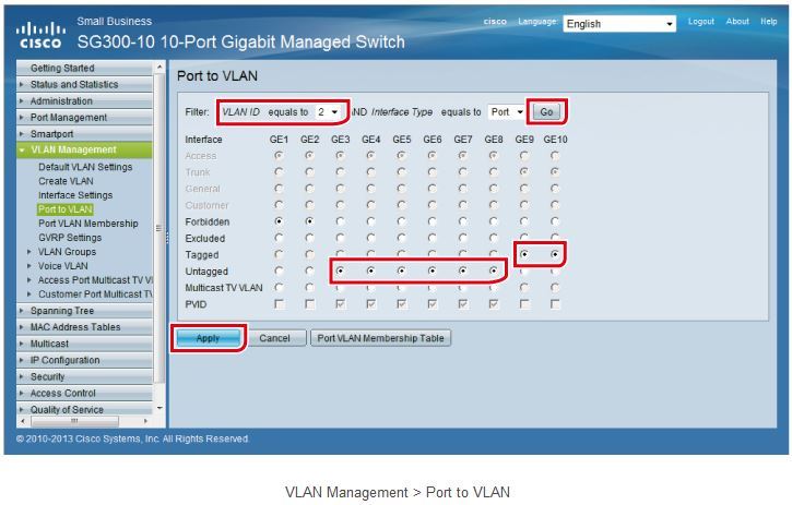
To switch to the settings for VLAN 2, set VLAN ID to “2”, and click “Go”. Ports 1 and 2 will not be included in VLAN 2, so set them to “Forbidden”. Ports 3 to 8 will be included in VLAN 2, so set them to “Untagged”. Ports 9 and 10 are the trunk ports, so set them to “Tagged”.
The VLANs (VLAN 1 and VLAN 2) have now been successfully created within the switch, and the trunk ports (ports 9 and 10) make it possible for these virtual networks to span across switches. Don’t forget to save the settings after you change them.