DME24N, DME64N Digital Mixing Engine
General Specification
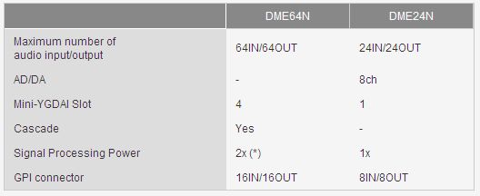
What is the difference between DME64N and DME24N?
There are differences in type and number of audio/control interface and signal processing power. Please refer the following table.
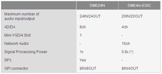
What is the difference between DME24N and DME4io-ES/C? Is it possible to use DME4io-ES/C for the similar purpose as DME24?
The following table shows the differences in specifications.
What is the difference between firmware V3.5x or earlier and V3.8 or later?
The hardware specification for DME Firmware V3.8x or later differs from the one for Firmware V3.5x or earlier. This change brings the following improvements.
- The maximum time for playing a WAVE file(.wav) on Wav File Player was increased.
- The memory capacity that can be saved via the File Storage function was increased.
- The DME unit can now be controlled by DME remote control protocol via Ethernet connection from certain external control devices.
- The DME24N/64N can now be set as the device group master when a device group is created, combining DME64N/24N and DME Satellite.
Audio Input/Output
Is it impossible to use the Mini-YGDAI cards with DME that don't appear in the Device Property dialog in DME Designer?
You can use such types of cards by selecting "MY-Others". It's possible to control/monitor the common functions through all types of Mini-YGDAI cards. However, the card-specific functions cannot be controlled by DME/DME Designer.
Does the maximum number of input/output channels depend on the sampling frequency (fs)?
The maximum number of input/output channels depends on the fs and the type of Mini-YGDAI card as follows.
When operating at fs=44.1/48kHz: DME24N : 24IN/24OUT (Internal AD/DA 8ch + Slot 16ch) DME64N : 64IN/64OUT (Slot 16ch x 4) + CASCADE 32IN/32OUT
When operating at fs=88.2/96kHz: (with NON High Sampling Rate compliant cards) DME24N : 16IN/16OUT (Internal AD/DA 8ch + Slot 8ch) DME64N : 32IN/32OUT (Slot 8ch x 4) + CASCADE 32IN/32OUT
When operating at fs=88.2/96kHz: (with High Sampling Rate compliant cards) DME24N : 24IN/24OUT (Internal AD/DA 8ch + Slot 16ch) DME64N : 64IN/64OUT (Slot 16ch x 4) + CASCADE 32IN/32OUT
In 88.2/96kHz, with NON High Sampling Rate capable cards, Mini-YGDAI slots work as 8IN/8OUT interfaces. On the other hand, CASCADE has 32IN/32OUT capability without depending on sampling frequency.
How can I input audio signal from a Microphone?
There are several ways to input mic level audio to DME64N.
Use the MLA8, 8 channel head-amp, in combination with the MY8-AD96 card. This is the simplest method for mic inputs. Use the AD8HR, 8 channel head-amp and AD converter, in combination with the MY8-AE card, etc.
This method allows you to remote-control the head-amp gain from the DME64N, and change the settings with a scene recall.
What is necessary to transfer digital audio signal between mixing console and DME64N/24N?
Putting Mini-YGDAI cards into both of a mixing console and DME64N/24N enables audio signal transfer by various protocol such as AES/EBU, EtherSound, Dante, and so on. In addition, DME64N can transfer 32 channel audio from/to a mixing console which is equipped with CASCADE interface, such as PM5D series and DM2000, without occupying any Mini-YGDAI slot.
Cascade
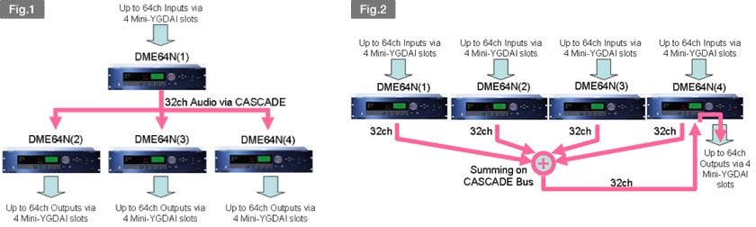
What is the advantage of cascading DME64N units together?
Via CASCADE connection, up to 32 channel audio can be transferred among up to 8 DME64N units. This feature enables the following applications.
Distribute audio signal from a DME64N into other units as shown as figure 1. The audio signal output from a DME64N to the CASCADE bus can be shared and used by other DME64N units interconnected by CASCADE cables as an input audio. The processed audio by the upstream DME64N can be distributed to the other downstream units without occupying any Mini-YGDAI slot, where they can be processed respectively for each specific purpose.
Thefigure 2 shows mix multiple audio signals output from DME64N units on a shared CASCADE bus. By this feature, multiple audio signals output from multiple DME64N units into a single CASCADE channel can be summed on it.
How far can cascade cables be extended?
Via CASCADE connection, up to 32 channel audio can be transferred among up to 8 DME64N units. This feature enables the following applications.
When cascading DME64N units together:
- At a sampling rate of 44.1kHz/48kHz: 100m
- At a sampling rate of 88.2kHz/96kHz: 30m
When cascading with the PM5D:
- At a sampling rate of 44.1kHz/48kHz: 200m
- At a sampling rate of 88.2kHz/96kHz: 100m
What can I do by cascading the DME-N with the PM5D series or DM2000?
You can transfer up to 32 audio signals from MIX/AUX/BUS of PM5D/DM2000 to DME64N, so that DME64N can be utilized as a output processor (GEQ, Crossover, Delay, etc) or a matrix mixer.
In addition, in a combination with PM5D, PEQ/GEQ or various type of effect unit realized by DME64N can be inserted into an arbitrary channel of PM5D. Furthermore, it's possible to control parameters in some type (*) of DME-N component from PM5D LCD screen.
Mixing
Which arbitary point can I listen to by using monitor function?
You can listen to the slot input, slot output, cascade output, or cascade input. However, you'll need to select the monitoring point in the LCD menu. Also, while an arbitrary monitoring point cannot be selected from the DME-N itself, you can specify it from DME Manager.
Why is the latency from input to output different among channels?
The audio latency from input to output may differ depending on Compile Priority setting. Compile Priority can be selected from the following two options.
[Resource]
When [Resource] is selected, a DME configuration is compiled so that as many components as possible can be deployed into hardware. With this option, the audio latency differs from path to path of audio signal.
[Fixed Delay]
When [Fixed Delay] is selected, a DME configuration is compiled so that delay time for every signal path can be identical. With this option, number of components which can be deployed into hardware is less than when [Resource] is selected.
Scene
What kinds of data are contained in a Scene?
A Scene contains a set of parameter values of all components in a configuration and settings for Local Link and Component Link.
Furthermore, each Scene can be programmed being associated with individual configuration. This means that recalling the next scene can totally switch the signal processing function in single DME unit.
How many seconds does it take to recall a scene?
The time it takes for a recall will depend on the number of parameters and on the state of the configuration.
If the scene change involves only simple parameter changes and does not change the configuration, the change will occur in less than a second. If the change involves a configuration change, it may take several seconds for the recall to occur, depending on the configuration.
Can the scene memories of all DME-N units on the network be recalled simultaneously?
Scene memories are recalled simultaneously for all DME-N units in the same Device Group. They cannot be recalled individually for each unit.
DME Designer
Is it possible to install both of DME Designer V3 and V4 into single PC and use them simultaneously?
No more than one version of DME Designer can be installed into single PC.
DME-N Network Driver (Ether-MIDI Driver) cannot be installed with the error message of "An additional MIDI Driver cannot be installed on this computer."
This is because the number of MIDI driver entry exceeds 10, the upper limit of Windows OS.
Especially Yamaha USB-MIDI driver consumes one entry for each USB port where a device is connected. So you may face this error message by connecting with a device using various USB ports.
In such a case, you have to uninstall unnecessary MIDI drivers from your PC, for example USB-MIDI driver. Then try to install DME-N Network Driver again.
Regarding how to uninstall Yamaha USB-MIDI Driver, please refer to the installation guide contained in a zip file of USB-MIDI Driver that can be downloaded from Yamaha Pro Audio Site.
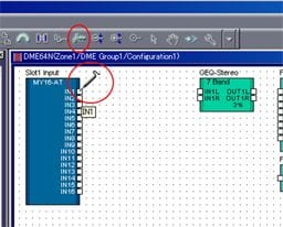
Audio signal does not flow even though wires seem to be connected among components in DME Designer Configuration window. What's wrong?
Crossed wires made by copying and pasting a wire onto another may not actually be connected. "Show Unconnected Node" function of DME Designer helps you to find such unconnected node in your configuration. Re-connecting the found floating node may solve your problem.
Why is it sometimes possible to place components even when the DSP Resource Meter exceeds 100%?
This is because the DSP Resource Meter is just a general guideline; only by actually compiling the data can to determine whether the components can be placed. Compilation uses a new algorithm that applies highly efficient optimization. This means that in some cases, it may be possible to place components even if the meter exceeds 100%.
Synchronize/Online
DME and DME Designer don't go ONLINE state. What should I check?
Check the following points:
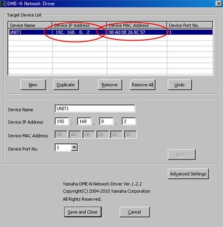
Has the latest DME Network Driver been installed on your computer?
On the DME Network Driver settings screen of the control panel, IP address and MAC address of the DME unit are set correctly?
On the firewall settings screen of your computer, has the DME Network Driver been excluded from the blocked objects? Are IP address and subnet mask of your computer set correctly?
Are appropriate cables used? DME64N/24N V3.5x or earlier does not support Auto MDI/MDI-X. So when PC and DME are connected directly via Ethernet cable, you may need to use a cross cable because
Are every Ethernet cable and switching hub connected correctly?
Did you try to switch the PC to another while DME Designer and DME are ONLINE?
If you unplug a Ethernet cable from a PC where DME Designer is running and ONLINE with DME units, the DMEs tries to keep the connection with the previous PC. When you try to go ONLINE from another PC under such condition, it may fail because the DMEs are already locked by the previous PC. If you need to switch the PC to alternative PC, please close DME Designer before unplugging Ethernet cable. If you encounter such symptom, please try to power cycle the DME and synchronize.
The control speed from DME Designer is too slow. What's wrong?
Are you displaying many meters on DME Designer? Displaying many meters at the same time which requires a lot of data traffic may result in such slow performance. If possible, please try to reduce meter display.
If you are using DME64N/24N whose firmware version is V3.5x or earlier with DME satellite, choosing satellite unit as a group master may improve the response speed.
Please check Link Mode of DME hardware. Changing this setting to 100BASE-TX may improve the performance.
Is it possible to import configuration data from a DME that has already been operating into a PC in order to revise its configuration?
If you have a project file (*.daf) whose configuration is identical with the one stored in the DME, you can retrieve the current parameter values from the DME by choosing synchronization direction "Designer <- DME option" in the Synchronization window. In other words, without the matched project file, you cannot import configuration data from the DME.
Considering maintenance work after starting operation, the project files should be managed strictly so that the system can be revised/improved in compliance with the customer's requests.
In order to manage the project files easier, the latest project file can be stored in the DME internal memory area by using "File Storage" function.
Does the PC have to keep ONLINE with the DME unit?
The unit needs to be connected only while transferring data or while editing parameters from DME Designer; it is not necessary to let the unit remain connected to the PC at other times.
Is it possible to connect multiple PCs to a single network and control the system from multiple DME Designers?
No, it's not possible. Only one PC (only one DME Designer) can control the DME network system at a time.
How long does it take to synchronize data between DME and DME Designer?
Amount of time for synchronization depends on both time to compile a configuration and time to transfer data.
The duration time to compile depends on complexity of the configuration. Small configuration takes only 2 or 3 seconds, however large configuration sometimes takes several minutes or more. In such a case, saving a project file after synchronization shorten the time to synchronize by skipping next compilation.
Regarding data transfer time, it varies depending on the number of Scene and number of DME units in a Device Group. However, once synchronization is performed, the data transfer time becomes shorter because only updated or additional parts are transferred.
Is it possible to use DME Designer V4 in combination with DME-N firmware V3?
No. Please download the matched version from Yamaha Pro Audio Site.
There are two different hardware specifications for DME: V3.5x or earlier; and V3.8x or later. Can they be used in the same system?
If DME Designer V3.8.x is used, that is compatible with all V3.x firmware versions, so it can design/control a mixed system (Device Group) with both V3.5x and V3.8x.
However, if you have both DME V3.5x or earlier and V4.00 or later, they cannot be used in the same system as is, because DME Designer V3.8.x is not compatible with DME firmware V4. It is recommended to downgrade the firmware V4.xx to V3.8x so that they can form single system.
Remote Control
What methods are available to control a DME remotely or making a DME work in conjunction with other equipments?
DME64N/24N can work in conjunction with various equippments connecting via GPI, MIDI, Remote, Ethernet. Each solution has each features.
GPI: It's possible to change arbitrary parameters of DME components or recall a Scene when the DME is triggered from hall installations, professional audio/video/lighting equipments via GPI. Additionally, DME can trigger such equipments when the DME's internal state is changed.
MIDI: In combination with mixing console or show controller that have MIDI communication capability ( Control Change, Parameter Change, Program Change), arbitrary parameters of DME components or Scene can be controlled remotly.
Remote: It's possible to realize highly integrated automation by developing PC application or touch panel UI such as AMX or Crestron using "DME Remote Control Protocol"(*).
Ethernet: DME Satellite and DME64N/24N firmware V3.81 or later can send/receive "DME Remote Control Protocol(*)" via Ethernet cable. This enables much flexibility in wiring compared to RS-422/232C cable.
* Please refer DME-N Remote Control Protocol Specifications for more detail.
What functionalities can be controlled from an external controller?
Every remote control method such as GPI, MIDI, Remote, Ethernet can control parameters of DME components in a configuration and can recall a scene. It's possible to make the association between incoming/outgoing signal(command) type and the parameter kind or event type by using DME Designer in Offline Mode.
Furthermore, DME Designer can be downloaded from Yamaha Pro Audio Site for free, so that you can know which parameters can actually be controlled from an external controller before purchasing equipments.
What are the spec for cable that can be used with control panels such as the CP4SF?
CPEV cable (city pair polyethylene insulated vinyl sheathed cable) with 0.65mm or greater diameter copper conductor and a length up to 100 meters can be used.
How far can the cable between a GPI controller and a DME be extended?
Although it depends on the anti-noise quality or environment, it's about 100 meters when CPEV cable with 0.65mm is utilized.
Can I connect multiple GPI switches to a single GPI IN?
Yes. Connect the switches in parallel to the GPI (+) and (-) pins. When you press one of the connected switches (for example), the specified scene will be recalled.
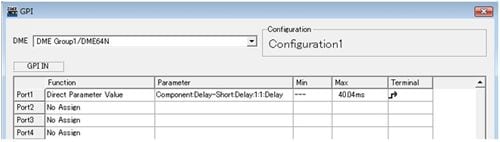
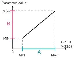
Can I specify the minimum and maximum value for GPI IN?
The following 2 types of settings allow you to adjust the parameter range for GPI IN signal.
A: It is possible to specify the incoming voltage range at each GPI IN port by defining MIN/MAX value in [Utility] -> [GPI] page in the DME unit or [Utility] -> [GPI] tab in the DME Desinger.
B: It is possible to specify the parameter value range by defining the parmaeter MIN/MAX value corresponding to GPI IN MIN/MAX voltage in [GPI] dialog box in the DME Designer.
GPI fader/volume controller does not work correctly. What should I check?
Please confirm the following points.
- Check if the cable is fixed firmly in the GPI connector on the rear panel of DME.
- Check if the GND terminals of DME and the controller are connected correctly.
- Is the cable disconnected? Or does the cable travel too long distance through noisy environment?
- Did you perform calibration after connecting the controller? You can calibrate GPI input voltage range in [Utility] -> [GPI] page in the DME.
- Check if the each GPI IN port is associated with the appropriate parameter kind correctly. Also check Min,Max,Terminal settings.
Please let me know about how to control a DME from an external controller via Remote/Ethernet.
Please refer DME-N Remote Control Protocol Specifications for details about how to connect/setup the DME and communication specification such as baud rate or command format.
In order to change the parameter continuously by using DME Remote Control Protocol, how frequently should the command be sent to the DME?
Although it depends on the whole system configuration and the complexity of DME configuration, command interval should typically be more than 60msec.
Can a DME64N/24N be controlled via Ethernet cable from an external controller?
A DME64N/24N whose firmware is V3.81 or later can be controlled via Ethernet cable by using DME Remote Control Protocol.
How can I control a DME64N/24N using physical faders and switches on a mixing console?
In combination with a mixing console that has MIDI communication capability, it's possible to control a DME unit remotely. When a Yamaha digital mixing console is utilized, the following settings are needed.
[With M7CL, LS9 series]:
- Set up the mixser's Control Change function (TABLE mode) so that MIDI control change messages can be transmitted when the parameters of particular channel are changed.
- With DME Designer, assign a DME component parameter kind that should be changed when the message is received on the DME.
- However, by this method, the parameters on the mixer side are also changed in parallel with transmitting Control Change messages, and of course it will effect on audio. For this reason, it's recommended that an unused mixer channel should be utilized for remote control purpose.
[With DM2000, DM1000, 02R96, 01V96]:
- Set up the mixer's Remote Layer (USER DEFINED) so that MIDI messages can be transmitted when the faders or switches are moved or pressed.
- The USER DEFINED function can send arbitrary format MIDI messages. This means not only Control Change but also Parameter Change and Program Change can be programmed to send to the DME.
- With DME Designer, assign the corresponding DME parameter kind for the Control Change/Parameter Change message. Also it's possible to assign Scene number for the Program Change message.
- It's an advantage that Remote Layer can control the DME without occupying any channel of the mixer.
[With PM5D]:
- Using MIDI REMOTE page on the PM5D, it's possible to transmit arbitrary MIDI commands without occupying any channel of the mixer.
System/Network design
What kind of switching hub can I use to connect among PC and multiple DMEs?
Full duplex 100BASE-TX switching hub is recommended.
1000BASE-T switching hub can also be used because it has compatibility with 100BASE-TX. however please note the theoretical maximum transmission speed is limited up to 100MBit/sec.
With either type of switching hub, the actual data transmission speed and distance are also depending on the performance of the switching hub and quality of the cables.
Is it possible for DME control network to co-exist with audio network such as CobraNet or EtherSound?
In theory, both can co-exist in a same LAN using single switching hub. However, it is highly recommended to divide the network by using VLAN function of the switching hub to prevent slow performance and low reliability of communication by huge amount of audio data traffic.
Is it possible to control a DME from DME Designer in an existing LAN where several PCs and other equipments are already connected?
If the LAN satisfies the following conditions, it's possible to control DME from DME Designer.
[Condition 1]:
The subnet mask of the LAN is "255.255.255.0".
Currently, DME works with the assumption the subnet mask of the connected network is "255.255.255.0". If the LAN has difference subnet mask configuration, DME cannot communicate with a PC correctly.
[Condition 2]:
The default gateway address is "***.***.***.254".
When a DME is controlled from a PC in other LAN, communications between them are generally performed via a gateway (router). Currently, DME works with the assumption the 4th digit of gateway IP address is "254". If the gateway has difference IP address, DME cannot communicate with PC correctly beyond subnet. (Please note this condition is not essential if DME is controlled from PC inside the same LAN)
In addition to these conditions, the following settings are required.
- Match the network address of DME with the one of LAN.
Please match the upper 3 digits of IP address of the DME with the ones of other PCs in the same LAN. For instance, if PC's IP address is "192.168.3.xxx", please assign "192.168.3.yyy" to the DME.
- Assign IP address to the DME not to collide with the other network equipments. Furthermore, if a DHCP server is running in the LAN, please configure it not to distribute the addresses that should be reserved for DMEs to the other equipments.
How can I determine IP address assigned to a DME64N/24N?
It is necessary to determine DME's IP address consulting with your network administrator because it should conform with the network policy. If no one administer the network, please assign the address taking note of the following points.
Assign the address that never collide with the other PCs, DMEs or Mixers that are connected to the same network.
If a DHCP server is running in the LAN, assign the address that is not delivered automatically by the DHCP server. Match the first three parts of IP address digits of the DME with the ones of other equipments in the same LAN.
If you would like to build a dedicated network for DMEs and DME Designer, generally a private address such as "192.168.xxx.yyy" would be chosen.
Hardware Specifications
What kind of cables fit the analog in/out Euroblock connectors on DME24N?
It is recommanded to use a cable whose diameter is from AWG16 to AWG24 (from 1.291mm to 0.5106mm) . Furthermore, if a stranded cable is utilized, it may be prone to breakage because of metal fatigue due to the weight of the cable or due to vibration. Please fix it on the DME24N unit to prevent such cable troubles.
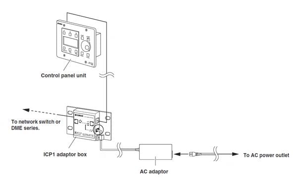
Does the ICP1 require a power supply?
ICP1 must be connected to the included adaptor box. Connect a network cable (CAT5) and power supply cable to the adaptor box. Within the adaptor box, the network signal and power supply are redistributed onto the CAT5 cable, and connected to the ICP1.
ICP1 does not conform with the standardized PoE (Power over Ethernet) specification.
How many languages can the DME-N's display show?
The user defined button titles can be shown in five languages; English, French, German, Spanish, and Japanese. However, all details in setting menus etc. are in English.
Maintenance
How can I initialize the DME internal memories?
Begin with the power turned off. Turn the power on while holding the [SCENE] and [ENTER] buttons and release them after the Yamaha logo disappears, then the initialization screen will appear. In the screen, 2 types of initialization way can be chosen.
Please refer the DME64N/24N owner's manual for more detail.
How can I update the DME64N/24N firmware?
Make sure to backup your project file (*.daf) before starting the update. Download the latest DME Designer and firmware from the Yamaha Pro Audio website.
1. Update DME Designer and DME-N Network Driver.
2. Update the firmware. Connect the PC where the DME Designer has been updated with the DME unit via Ethernet or USB cable. Then Begin the update process by selecting [Hardware] -> [Firmware Update] -> [Program+Component] in the DME Designer. Please refer the DME64N/24N owner's manual for more detail.
3. After the update is done, the DME unit will restart automatically. It is needless to initialize the internal memory of the DME unit.
4. Restart the DME Designer.
How can I upgrade my DME64N/24N V3.5x to V3.8x or V4.0x?
The hardware specification for DME Firmware V3.8x or later differs from the one for Firmware V3.5x or earlier. Therefore firmware V3.5x or earlier cannot be upgraded to V3.81 or later by yourselves. Also, firmware V3.81 or later cannot be downgraded to V3.5x or earlier. If you need to upgrade your DME from V3.5x to V3.8x, your Authorized Service Facilities can provides charged upgrade. Please contact your Yamaha dealer.